


Introduction:
The buildings and structures shall be protected from lightning strikes by installing well designed and executed lightning protection system (LPS). It usually consists of both external and internal lightning protection system. There has to be proper co-ordination between the design and execution to ensure the protection.
An external Lightning Protection System consists of,
1) Air terminals
2) Down conductor
3) Test link
4) Earthing system.
5) Clamps & Fixture
Installation of Lightning Protection system:
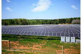
If the roof or wall is made of non-combustible material then the components of LPS can be directly mounted on the surface of a wall. Spacers and fixtures made of both conductive or non conductive materials shall be used for clamping the conductors on the roofs.
If a roof or wall constructed from combustible material, then even the temperature rise due to the flow of lightning impulse current may result in fire or explosion. Hence, IS/IEC 62305-3 insists that special care is required for installation of lightning protection system. The effect of heating on the roofs made of combustible material due to lightning impulse current shall be reduced by implementing the following measures:
- The cross-sectional area of the conductors shall be increased;
- The distance between the conductors and the roof covering shall be increased and
- A layer made of heat-protective material shall be provided between the conductors and the flammabe material.
For the structures with flat roofs, the conductors laid on the perimeter of the structures should be installed as close as possible to the outer edges of the roof. T down conductor should be installed in the shortest possible path between the air terminal and earthing system. The number of bends should be as low as possible with least possible joints.
IEC 62305-3 suggests the distance required between the supporting fixtures for both Flat and round rod configurations of down conductors. The spacing details are as follows,
For structures with a roof ridge, the conductor should be installed on the roof ridge. For small structures if the structure is protected by the roof ridge conductor, then at least two down - conductors should be installed at the opposite corners of the structure. The instructions given by IEC 62305-3 for installation of air terminal and down conductor for sloped roof are shown below.
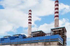
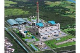
If the structure has chimney at the top then a separate air terminal rod of suitable height shall be installed for protecting the chimney. It should be ensured that the protection angle provided by the air terminal at the required level is sufficient for protecting the chimney.
If the gutters have sufficient thickness and cross-sectional area as specified by IS/IEC 62305-3 then they can be used as natural components for down conductors The down conductor should not be installed in gutters or water spouts as the corrosion rate will be higher because of the moisture content.
IS/IEC 62305-3 suggests that any metallic structures or pipe lines running adjacent to the down conductors should be connected to establish equipotential bonding for avoiding the potential difference is voltage during the passage of electric current. The test link shall be installed at a height of around 1m to 1.5m above the ground level and the earthing conductors shall be laid at a depth of 0.5m below the ground level.


Follow Us